Analysis of the influence of the earthing resistance of pylones on the performance of the HVAC line facing electromagnetic transitories lightning
Prossor Anthony Bassesuka Sandoka
Electrical Engineering
ISTA Kinshasa
Kinshasa, DR Congo bass_sandoka@yahoo.fr
Abstract— The large amounts of energy transmitted through power lines force them to operate more and more within their limits, and unscheduled outages increase the risk of instability. Lightning discharges is the main cause of unscheduled power line cuts [10]. This present article deals with the analysis of the behavior of an HV line during atmospheric discharge and evaluates the spatio-temporal distribution of the wave of the lightning current by the implementation of the "double exponential" function, the function of " of Heidler "(sometimes a combination of these two functions) and engineering models (transmission line models) [8].
Knowledge of the lightning current wave distribution has allowed us to quantify the induced voltage as a function of the equivalent impedance when the lightning falls at the top of the pylon, the voltage due to the lightning current wave reflected through the pylon and the tension at the top of the pylon.
The objective of our study falls within the framework of the simulation of the influence of the resistance of the earthing of pylons on the performance of HV lines subjected to fast front transients due to lightning. The case study is carried out on the 220 Alternating current kilovolts (kV AC) LIMINGA-FUNA line in the Democratic Republic of Congo, located in a region where thunderstorm activity is very important.
The implementation of Ohm’s law, the telegraph equations and the FDTD method as well as the theory of transmission lines, has been the subject of the modeling of voltages induced on the HV line as a function of the resistance to grounding. land of pylons. Thus, the use of platforms such as Matlab / Simulink and Excel, allowed us to simulate the influence of the resistance of pylon earthing on lightning strikes.
Simulation results obtained in this paper show that the value of the grounding resistor of lower towers or also 10 Ohm damped wave atmospheric overvoltage and ensures good insulation coordination of the line elements.
Since it is difficult and expensive in some areas to achieve very low values of earth resistance of the towers, we recommend choosing a few pylons for which should improve these resistances. In addition, to prevent the propagation of high voltages to the substations, it is imperative to minimize the earthing resistances of the pylons up to 2 Kilometer (km) from the substation. The use of surge arresters with low earthing resistances is also essential.
It should be noted that our study contributes to the analysis of the influence of earthing on the performance of HVAC lines in the face of electromagnetic lightning transients that can disrupt network operation.
Keywords— Earthing of HV lines, electromagnetic lightning transients, telegraph equations, the FDTD method, Modeling
I. INTRODUCTION
The high and medium voltage electrical networks in their transport and distribution phase are exposed to disturbances during a lightning discharge which is a high frequency electrical phenomenon which induces overvoltages on all conductive elements and particularly on wiring and electrical equipment. These disturbances also often contribute to the total or partial destruction of equipment for the production, transmission and distribution of electrical energy.
However, the mechanism of creation of lightning is more complex, the lightning discharge current can be in the range of 3 to 200 kiloAmpere (kA), about 1 percent (%) is 140 kiloAmpere (kA) or more, while about 50 percent (%) exceeds 25 kiloAmpere (kA). There are two impacts of lightning: The direct impact (thermoelectric effect) results in the circulation of a strong electric current that heats the material and because of the often very significant mechanical damage, even spectacular. And the indirect impact (electromagnetic effects) manifests itself in the appearance of lightning current and induces on the one hand, a common mode voltage and an electromagnetic field of exceptional intensity by virtue of the Maxwell-Ampere equation.
The objective of the work exposed in this article is devoted to the study, the modeling and the simulation of the influence of the resistance of the earthing of the pylons on the performance of HV lines subjected to electromagnetic lightning transients, including the application is made on the 220 Alternating current kilovolts (kV AC) LIMINGA-FUNA line in the Democratic Republic of Congo, located in a region where thunderstorm activity is very important.
To achieve this goal, we have implemented Ohm's Law, Telegraphist's Equations and FDTD Method as well as Transmission Line Theory for modeling the voltages induced on the HV line as a function of the reset resistance Earth. Thus, the use of platforms such as Matlab / Simulink and Excel, allowed us to simulate the influence of the resistance of the pylon earthing on the performance of HV lines against lightning strikes.
II. DEVELOPMENT
It is possible to reduce the number of tripping of power lines due to lightning by the proper installation of ground wires and good grounding of the line. In regions with a high keraunic level, reducing insulation failures due to lightning is therefore a concern of overhead line designers.
Using Kirchhoff's laws, telegraph equations and the FDTD method as well as transmission line theory, in this article we will address the following aspects:
![]()
pylon;
![]()
wave;
![]()
earth resistance of the pylons.
Calculations will be made to the 220 Alternating current kilovolts (kV AC) LIMINGA-FUNA, located in an area where thunderstorm activity is very high while limiting our calculations the aspects of lightning from the line in relation to the ground pylons.
A. Electromagnetic interference
Any electromagnetic interference situation involves three different elements: a source of disturbance emission, a disturbance receiver (victim), and a coupling mechanism by which the disturbance reacts to the operation of the receiver.
1) The source of disturbance
Sources of electromagnetic disturbance can be characterized by:
![]()
![]()
![]()
2) Electromagnetic coupling
Coupling is the phenomenon of propagation of disturbances which occurs between the source and the victim. The coupling modes can be classified according to the type of disturbance and according to the propagation medium, by conduction (characterized by currents and potential differences), or by radiation (characterized by electric and magnetic fields).
B. Lightning and aggression mechanism
The template is used to format your paper and style the text. All margins, column widths, line spaces, and text fonts are prescribed; please do not alter them. You may note peculiarities. For example, the head margin in this template measures proportionately more than is customary. This measurement and others are deliberate, using specifications that anticipate your paper as one part of the entire proceedings, and not as an independent document. Please do not revise any of the current designations.
Lightning is defined by the passage of a very large transient
current between two points normally isolated from the atmosphere. Lightning occurs between a cloud and the ground, between two clouds, or between two charged areas within a single cloud. These stored charges are, in all likelihood, generated by the movement of hot air in a forming cloud. Lightning being one of the unpredictable and harmful natural phenomena has been mentioned by several researchers [2]. Famous researcher Benjamin Franklin alluded to when demonstrating a decade ago that his electric shock is gigantic. These various studies have made it possible to classify lightning strikes into different categories which are based on two important criteria :
![]()
![]()
1) Lightning electrical parameters
The electrical parameters of lightning are:
![]()
![]()
![]() field
field
2) Lightning strike on a line
The general empirical formula indicating the lightning strike (total number of Lightning Strikes per year) of a line (pylons, phase and guard cables) is given by [9] :
NL= Nk .(N130 l70)..L100 (1)
Nk = keraunic level;
NL = lightning strike of the line,
N1 = lightning strike of the highest horizontal conductor;
L = length of the line in km;
![]() = width
of the line in m (between the outer conductors); β = influence factor of
pylons and earth cables.
= width
of the line in m (between the outer conductors); β = influence factor of
pylons and earth cables.
C. Elements influencing the behavior of lightning in the ground
The grounded are vital electrical circuits and elements are essential in the protection against electrical accidents. Elements influencing the behavior of lightning on the earth network are:
- Soil type ;
- Soil resistivity ;
- Resistance ;
- Permittivity ; - Permeability.
D. Modeling of the wave of the lightning current [8]
This current is of a pulse nature, and its shape is characterized by a peak value, a rising edge to the peak (or rise time) and a decay time.
1) The exponential double function
The exponential functions are used by a certain number of authors and which have the advantage of having analytical Fourier transforms, which makes it possible to carry out a direct analysis in the frequency domain.
i(t)=I0 exp(At)exp(Bt) (2)
I0 : is the amplitude of the base current, A and B are time constants.
2) The function of Heidler
The analytical expression of the current at the base of the lightning channel was presented by Heidler in 1985. The use of the latter gave results which correspond better to the experimental observations, this function is modeled as follows :
i(0,t) = I0.t1n1+t1n.exp(t2 (3)
I0: Amplitude of the base channel current;
1: Rise time constant 2: Fall time constant; η: correction factor of the amplitude of the wave and n: is an exponent varying between 2 and 10.
Below are the lightning current parameters in relation (4) above, for n = 10. These parameters depend on the protection level.
Table 1: Lightning current parameters [5]
|
Parameters |
First strike |
Consecutive short strike |
||||
|
Level of protection |
Level of protection |
|||||
|
I |
II |
III- IV |
I |
II |
III-IV |
|
|
I0 |
200 |
150 |
100 |
50 |
37,5 |
25 |
|
η |
0,93 |
0,93 |
0,93 |
0,993 |
0,993 |
0,993 |
|
1 |
19 |
19 |
19 |
0,454 |
0,454 |
0,454 |
|
2 |
485 |
485 |
485 |
143 |
143 |
143 |
i(0,t)= I011.t11n1 1+t21 n1.exp(t22+ I022.t11n2
1+t21 n2.exp(t22 (4)
The following table 2 presents the standard parameters of Heidler functions corresponding to the first arc and the return arc of a typical lightning strike [5] [8].
Table 2: Parameters of a lightning strike [5] [9]
|
Parameters |
First arc |
Back arc |
|
I01 |
28 |
10,7 |
|
11 |
1,8 |
0,25 |
|
21 |
95 |
2,5 |
|
1 |
2 |
2 |
|
I02 |
- |
6,5 |
|
22 |
- |
230 |
|
2 |
- |
2 |
3) Transmission line model [7]
This model assimilates the lightning channel to a lossless transmission line where a current pulse propagates from the ground at a constant speed of the return arc "v". The spatio-temporal distribution of the lightning current is defined by:
![]() (5)
(5)
𝑧′ > 𝑣. 𝑡 → 𝑖(𝑧′, 𝑡) = 0 (6)
E. Lightning current wave propagation circuit model
1) Equivalent impedance encountered by the lightning current wave [1]
Zi: is the equivalent impedance encountered by the current wave when it falls on the top of the pylon, it is given by the relation :
![]() (7)
(7)
2) Pylon current wave propagation impedance [11]
The propagation impedance of a pylon depends on its geometric shape. It can be calculated by the following relations :
![]() (8)
(8)
![]() (9)
(9)
Relations (8) and (9) correspond respectively to the cone and cylinder models.

Fig 2: Models for the calculation of the propagation impedance of a pylon [11]
3) Constant wave impedance over which all current components operate to contribute to the voltage at the top of the pylon [1]
Zℵ: Is the constant wave impedance over which all components of the current operate to contribute to the voltage at the top of the pylon.
![]() (10)
(10)
4) Current wave propagation impedance of the keep wire
The earth wire propagation impedance is given by the following formula:
![]() (11)
(11)
5) Electric model of pylons earth network
At very high frequencies, the behavior of earthing is very different from that at power frequency. The electrical circuit below is a representation of a portion of the π model of the HV power pylon earth network. [10] [12].

Fig 3: Representation of an earth electrode
The governing formulas for determining the resistance, inductance of capacitor capacitance and conductance of an earth network are:
![]() (12)
(12)
![]() (13)
(13)
![]() (14)
(14)
![]() (15)
(15)
![]() (16)
(16)
Where: 𝑙: Length of the electrode segment in m; µ0: Permeability of vacuum 4π × 10−7 kg m A − 2 s − 2, 𝑟: Radius of the electrode in m; 𝜌: the resistivity of the ground in Ω.𝑚; ℎ: Burial depth of the earthing electrode in m; 𝜀: Permittivity in 𝐹.𝑚 − 1.
F. FDTD modeling of voltage and current induced by electromagnetic lightning transients
The diagrams below represent a branch of an electricity pylon which is modeled as a transmission line, we apply Kirchhoff's law for the resolution and the FDTD method.

Fig 4: Long arm of the electricity pylon
We show the following equations:
𝑣(𝑥 + ∆𝑥, 𝑡) = 𝑣(𝑥, 𝑡) − 𝑅. ∆𝑥. 𝑖(𝑥, 𝑡)
![]() (17)
(17)
Similarly, we can get the equation for the second transmission line by:
![]()
∆𝑥, 𝑡) (18)
By solving equation (17and 18) by the FDTD method, we obtain the induced currents and the voltages induced by the electromagnetic effects:
![]() (19)
(19)
![]() (20)
(20)
1) Tension model at the top of the pylon
The voltage at the top of the pylon, taking into account the successive reflections of the wave through the pylon is given by relation [9]:
𝑉𝛾(𝑡) = 𝑉𝑖(𝑡) + 𝑉2(𝑡) (21)
Vi (t) is the voltage induced by the spatiotemporal distribution of the lightning current wave meeting the equivalent impedance as it falls at the top of the pylon.
Vi (t) = Zi .I(t) (22)
Zi: is the equivalent impedance encountered by the current wave when it falls on the top of the pylon.
V2 (t): is the voltage due to the current wave of the lightning reflected through the pylon. It is given by the relation:
![]() (23)
(23)
2) Tension at the foot of the pylon
The voltage at the foot of the pylon at a time is due to the components below [9].
- the voltage wave which arrives at the foot of the pylon at time t and which is refracted
- voltage waves due to the various reflections at the head of the pylon at times t -2nτT and which are refracted.
It is then given by the relation:
𝑉𝜕(𝑡 + 𝜏𝑇) = 𝛼𝜕𝑍𝑖[𝐼(𝑡) + ∑𝑁𝑛=1 𝐼(𝑡 − 2𝑛𝜏𝑇) . 𝜓𝑛] (24)
3) Tension on the insulator string
The voltage at any point of the pylon (at the level of the insulator string) is given by the relation [9]:
![]()
2𝑚𝜏𝑇−𝜏𝜑) . 𝜓𝑚] (25)
III. SIMULATION
A. Considering the pylon earthing resistance at 10 Ohm Ω
The 220 kV LIMINGA-FUNA HV line in DR Congo /
KINSHASA is the main energy supply corridor for the city of Kinshasa in the eastern, central and northern parts. She is currently experiencing several triggers mainly due to:
1) frequent overloads because it is at the limit of its transit capacity: indeed, it does not reach its thermal limit but trips because of the voltage drop;
2) lightning discharges: it is quite rare that a thunderstorm that occurs in one of the areas crossed by this line cannot trigger a trigger.

Fig 5: Geometric characteristics of the 220 kV line [15]
By applying relations (7) and (12) to the line of figure 5, we obtain for the wave impedances of the pylon and the ground wire respectively 159 Ohm (Ω)and 563 Ohm (Ω).
We simulate:
• The induced voltage Vi(t) is the voltage induced by the spatiotemporal distribution of the lightning current wave meeting the equivalent impedance when it falls at the top of the pylon.
• the voltage V2(t) due to the current wave of the lightning reflected through the pylon.
• The tension at the top of the pylon.
• Influence of the earthing resistance on these two parameters.
With Avec 𝑖(𝑡) = 𝐼𝑜(𝑒−𝐴𝑡 − 𝑒−𝐵𝑡) which is the lightning current along the pylon. In the case of a direct impact with the following characteristics: I0 = 100 kA, 𝐴 = 0,003 𝑆−1, 𝐵 = 105𝑆−1, from the equation of the voltage due to the wave of the lightning current reflected through the pylon, we made our simulation which gave the following results.
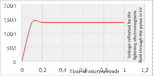
Figure 6: Voltage reflected by the electromagnetic field of lightning through the pylon in kV with R = 10Ω pylon resistance
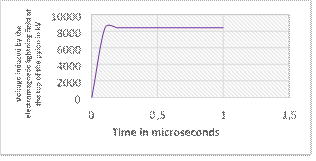
Figure 7: Voltage induced by the electromagnetic lightning field
at the top of the pylon in kV with R = 10Ω pylon resistance
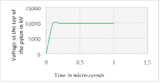
Figure 8: Voltage at the top of the pylon in kV with R = 10Ω pylon resistance
 Time in microseconds
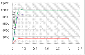
Fig 9 : Superposition curves
In the case of a lightning strike at the top of the pylon, the results presented in Figures 6, 7 and 8 show that the risk of bypassing the insulator of a line depends mainly on the following factors:
![]() f
the lightning current wave (peak value,
f
the lightning current wave (peak value,
rise time, etc.);
![]()
(height, span, position of the phase.
The lightning current wave induces a surge at the top of the pylon, varying almost linearly with the impedance of the pylon. This shows that the return arc is more restrictive and contributes to the risk of bypassing the insulators because this overvoltage reaches critical values in this case 10.000 kV. The reflection of the lightning wave generates a voltage surge with a maximum amplitude of 1400 kV, which can also disrupt the operation of the electrical energy network.
IV. ANALYSIS OF THE INFLUENCE OF EARTH RESISTANCE ON LINE PERFORMANCE
A. To peak voltage as a function of the pylon earth impedance, first arc
To check the influence of earth resistance on line performance, we will consider the lightning current waves, the parameters of which are presented in table 1, for protection levels III-IV (as a reminder, the values peak lightning currents are 100 kA for the first arc and 20 kA for the return arc). This choice is explained by the fact that the peak current values of these waves are close to the values recommended in the literature, after several measurements of real lightning strikes [1]
The lightning current causes an extremely rapid change in the electromagnetic field and the waves induce surges in conductors located far from the point of impact; its effects are felt several kilometers away.
A lightning strike falling near a line develops a magnetic induction field large enough to create an induced overvoltage, the order of magnitude of which is expressed by the expression:
![]() (26)
(26)
With: 𝑍𝑂 characteristic impedance of the line in Ω.
![]() (27)
(27)
𝐼0 : Lightning current which varies from 20 kA à 100 kA ;
ℎ : driver height in m ;
𝑑 : distance between the line and the point of impact in m or km.
Hence
:![]() (28)
(28)
Consider, as an indication, a three-phase 220kV power transmission line whose insulators have a shock wave withstand of 450 kV. It is assumed that the resistance of the earth electrodes is 25 Ω.
In normal situation, no current circulates in the earth electrode and the voltage between a phase and the earth is 127.2 kV.
Suppose a lightning strikes one of the pylon releasing a current of 20 kA according to the figure below. This current flows through the earth electrode resistor and causes a voltage drop in it which is equal to:
𝑉 = 𝐼0 × 𝑅 (29)
𝑉 = 20.000A×25= 500.000V= 500 kV.
Between the phase and the ground, a transient overvoltage is: of the order of:
𝑈𝑖 = 𝑉𝑃𝑁 + 𝐼0 × 𝑅 (30)
𝑈𝑖 = 𝑉𝑃𝑁 + 𝐼0 × 𝑅 = 500+127,2 = 627,2 kV,
Between the phase and the ground, a transient overvoltage of the order of 627.2 kV appears which is greater than the withstand voltage of the insulators. This overvoltage causes a bypass arc which ignites between the terminals of the insulator strings and the 3 shortcircuited phases and consequently, the opening of the circuit breaker. The figure below shows the contribution of the earth resistance on the damping of the transient overvoltage induced by the electromagnetic field and the waves of 20 kA in the conductors located far from the point of impact.
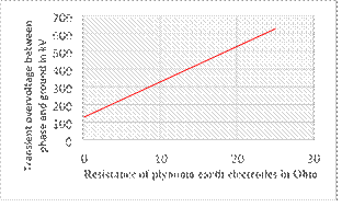
Fig 10: Peak voltages as a function of the pylon earth impedance, consecutive short stroke.
We find that, the transient overvoltage induced by the electromagnetic field and the waves of 20 kA in the conductors located far from the point of impact, is a linear function of the grounding impedance of pylons. It is evident that the risk of bypassing the insulator of a phase depends essentially on the earth impedance of the pylon, on the characteristics of the lightning current wave (peak value, rise time, …) And the geometric characteristics of the pylon and the line (height, span, position of the phase,…).
V. CONCLUSION
The concept of grounding involves several fields of research. The operation of electrical installations depends closely on the way in which certain devices are earthed and on the values of the earthing parameters (resistance, inductance, capacitance, etc.). In view of the simulation results, for the LIMINGA-FUNA line in Kinshasa, the value of 10 Ω for the pylon impedance is a reasonable limit for the risk of bypassing the insulator in the event of a lightning strike at the top of the pylon for the first arc (25kA). But for the return arc (100 kA) taken in this case, bypassing the isolator is inevitable.
The lightning current wave induces a surge at the top of the pylon, varying almost linearly with the impedance of the pylon. This shows that the return arc is more restrictive and contributes to the risk of bypassing the insulators because this overvoltage reaches critical values in this case 10,000 kV. The reflection of the lightning wave generates a voltage surge with a maximum amplitude of 1400 kV, which can also disrupt the operation of the electrical energy network.
The transient overvoltage induced by the electromagnetic field under waves of 20 kA in conductors located far from the point of impact is a linear function of the earth impedance of pylons. It is evident that the risk of bypassing the insulator of a phase depends essentially on the earth impedance of the pylon, on the characteristics of the lightning current wave (peak value, rise time, …) And the geometric characteristics of the pylon and the line (height, span, position of the phase,…).
It should be noted that our scientific research contributes to the analysis of the influence of earthing on the performance of HVAC lines in the face of electromagnetic lightning transients that can disrupt network operation.
Since it is difficult and expensive in some areas to achieve very low pylon earth resistance values, it is recommended to choose a few pylons for which these resistances should be improved. In addition, to prevent the propagation of high voltages to the substations, it is imperative to minimize the earthing resistances of the pylons up to 2 km from the substation.
We also recommend that the use of surge arresters with low earthing resistances is also a must.
VI. BIBLIOGRAPHICAL REFERENCES
1Tuan Tran Quoc. Modeling and improving the performance of electrical networks, HAL Id: tel-00693877 https://tel.archives-ouvertes.fr/tel00693877 Submitted on 3 May 2012.
2Tahar ROUIBAH Theme. Contribution to the modeling and simulation of the earth connections of electrical installations. Doctoral thesis, Defended on: 11/11/2015.
3Ali Jazzar. Electromagnetic Modeling of a Lightning Shock in Aeronautics. Electric energy. University of Grenoble, 2012. French. fftel00789991v1f.
4KEVIN APOTE A . TETE. Transient response of lightning strikes on memory wind installations presented as partial requirement of the master's degree in engineering. June 2019.
5Jean-Pierre NZURU NSEKERE. Contribution to the analysis and realization of the earthing of electrical installations in tropical regions
February 2009
6S. Kaouche, B. Nekhoul, K. Kerroum and K. Drissi, "Induced Disturbance in Power Network by Lightning," in Journal of Communications Software and Systems, vol. 3, no. 1, pp. 52-58, March 2007, doi:
10.24138/jcomss.v3i1.269
7V. Javor and P. Rančić, "On the Choice of the Lightning Channel Current Decay Constant in the Modified Transmission Line Model with Exponential Decay," in Journal of Communications Software and Systems, vol. 5, no. 4,
pp. 135-139, December 2009, doi: 10.24138/jcomss.v5i4.199
[8]Boutaayamou M., Sabariego R.V. and Dular P., 2008] An iterative finite element perturbation method for computing electrostatics field distorsions, IEEE Transactions on Magnetics, vol. 44, n° 6, June 2008, pp. 746-749.
[9] International Electrotechnical Commission (IEC), 2006: IEC 62305-01: Protection against lightning - Part 1: General principles, first edition 200601.
[10]Kiessling F., Nefzger P., Nolasco J.F., Kaintzyk U., 2003. Overhead Power Lines, Planning, Design, Construction, Springer-Verlag Berlin Heidelberg, Germany, 2003.


